Structural Welding and Steel Frame Details
The welds at the joints comply with current specifications according to DIN 4100 and DIN 1913 for electrodes. The quality of arc welding adheres to the EN ISO 15614:2017 standard. All metal part welds are executed using continuous seam arc welding or Kb 7018 electrodes.
Special attention is given to the connections of individual frame elements (load-bearing structure). To prevent corrosion, the sections are sprayed with an appropriate protective spray.
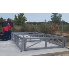
The frame is hyperstatic, providing increased strength and stability. This design makes the structure more resistant to failures and collapses by distributing loads across multiple points. If a joint or beam fails (e.g., due to an accident involving a vehicle), the rest of the structure can continue to bear loads, creating a protective cage that allows users to exit safely.
The frame exhibits minimal deformations under loads or temperature changes, highlighting its durability. Additionally, it has high resistance to dynamic loads, as it is engineered to absorb and distribute energy effectively.
The frame undergoes pre-stressing, achieved through a specific welding sequence. This process is applied mainly to long units to prevent excessive bending. In modular configurations, connections are made at the top, middle, and bottom of the columns, and in special cases, at the roof or base beams. Once the panels are installed, the entire structure achieves full rigidity, preventing oscillations due to dynamic loads.
Steel Quality
The steel used is Fe 360 S235JR (St 37-2), in accordance with DIN 17100 specifications.
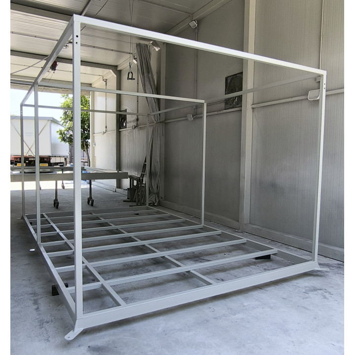
Base Frame
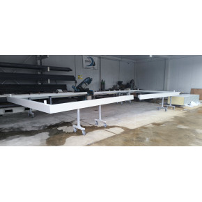
The unit's base frame consists of a perimeter frame made of RHS 100x50 mm steel sections with a minimum thickness of 3.0 mm. Intermediate SHS 50x50 mm crossbeams (3.0 mm thick) are placed parallel to the short side of the unit, with a maximum spacing of 61 cm.
For units wider than 2.00 m, additional SHS 50x50 mm transverse beams are installed parallel to the long side, with a maximum spacing of 1.25 m, reducing deflection.
For units wider than 2.60 m, SHS 50x50 mm beams are welded between the crossbeams to form a grid structure, ensuring full plywood subfloor support. In smaller units, this is naturally achieved without additional beams.
The construction is rigid, free from deformations or excessive deflections. The base is designed to accommodate non-uniform ground conditions, relying on multiple anchoring points at each column base.
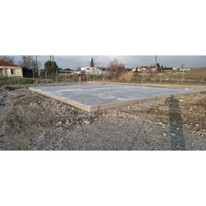
The anchor points, protruding below and laterally, are designed for bolt fastening to a concrete foundation. They measure 14x70x10 mm or 80x50x10 mm, with at least one Ø18 mm hole per point. Each unit has a minimum of four anchoring points, with an additional one every 3 meters in length.
Special consideration is given to safe transport and securement on vehicles. Optional metal sleeves can be installed at the base to allow transportation by container trucks.
The structural sizing ensures the required strength and rigidity for mobile floor loads.
Structural Frame Elements
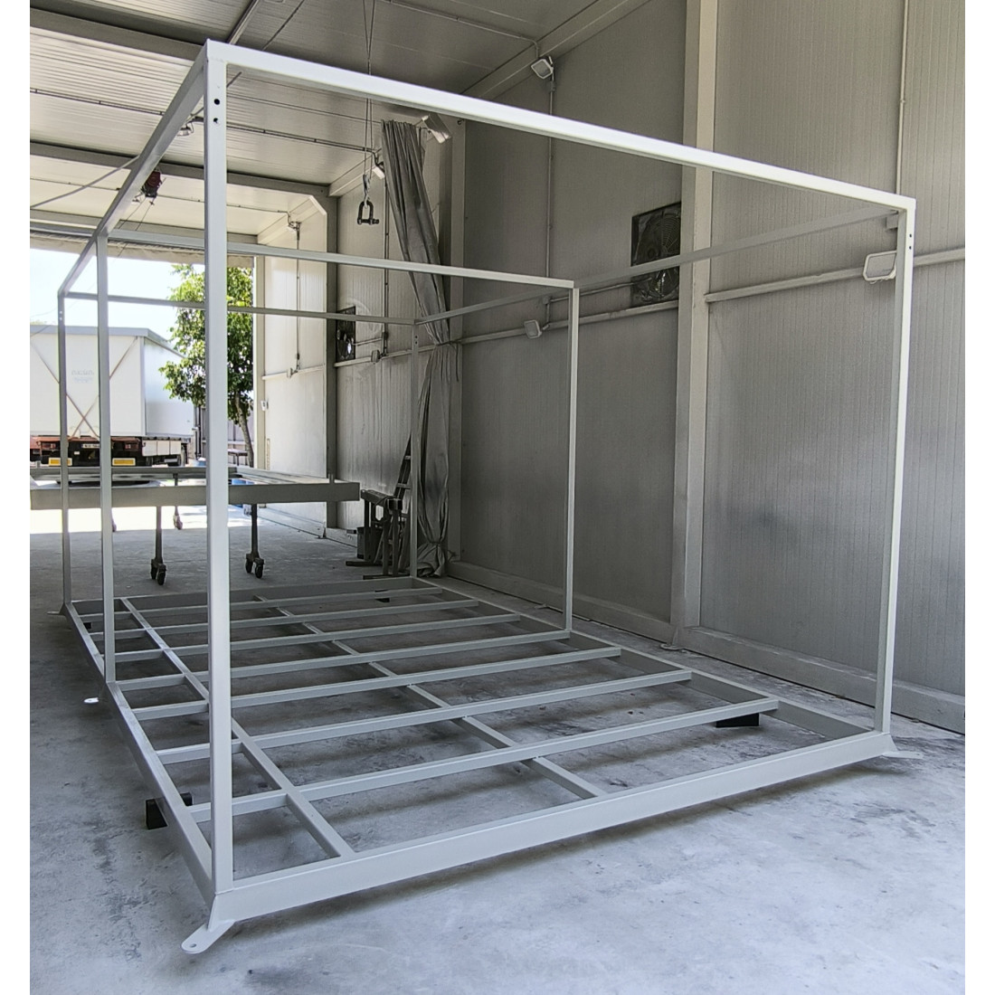
The load-bearing elements (columns and beams) are entirely made of steel sections, with a minimum SHS 50x50 mm, 3.0 mm thickness for single-story units and 4.0 mm thickness for multi-story units.
The section sizes and connection methods provide full rigidity, eliminating twisting, deformation, or bending deflection.
Each unit has a minimum of four columns, one at each corner. If required, additional intermediate columns are placed to ensure a maximum axial spacing of 3.0 m (as determined by structural analysis).
For example, a 6.00 x 2.50 x 2.50 m unit has six columns.
The frames of individual modules are joined using at least:
-
Three M14/140 bolts per column
-
Three M14/140 bolts per roof beam connection
-
Two M8x20 bolts per gutter joint
-
Bolted connections for bases, stairs, and accessories
The unit includes a permanent or removable lifting system. In the removable version, lifting attachments are bolted onto the frame and removed after installation, with corner reinforcements reinstalled.
Each module has a minimum of four double Ø18 mm holes for bolted lifting attachments, which are returned to the factory after use. This patented lifting system enhances anti-theft protection.
Anchoring and Load Transfer
The unit has at least four permanent anchoring points (100x70 mm) welded to the frame with 40/80 mm triangular reinforcements, all with a minimum thickness of 6 mm and capable of supporting at least 500 kg each.
Each anchoring point includes an Ø18 mm hole for securing the unit with M14x170 mm bolts. These ensure the safe transfer of imposed loads to the foundation, preventing movement or deformation of the unit.
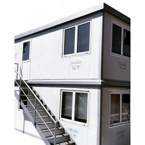
Dimensions, Construction, and Features
Height:
-
Standard: External height 2.50 m, internal height 2.27 m
-
Optional: High Cube with external height 3.00 m, internal height 2.77 m
Construction Type:
Frame:
Steel (ELOT EN 10025):
Hot-rolled steel strip in the following steel grades:
-
S235JRH
-
S275JOH
-
S355J2H
-
S460MH
Finish:
Openings:
-
Default: No openings
-
Optional:
-
Single-side unit connection openings: 3 Ø16 mm holes per column and ridge beam
-
Two-side unit connection openings: 3 Ø16 mm holes per column and ridge beam
-
Electrical installation openings: Pre-drilled at selected positions on columns and roof beams
Coating:
Lifting System:
-
At least 4 lifting points
-
Default: Removable lifting system (lifting hooks are detached after installation and remain company property)
-
Optional: Permanent lifting system
Anchoring:
Roof Type:
Energy Insulation (Walls & Roof):
-
Select the panel thickness to adjust external frame dimensions accordingly
-
Default: 40 mm sandwich panel
-
Optional: 50 mm, 60 mm, 80 mm, or 100 mm sandwich panels
Warranty
Construction Time
Transport
- The transportation of the frame can be carried out using a conventional flatbed truck for widths up to 2.5 m, and a special transport truck for widths of 3.0 m.
- The transportation cost is calculated based on the length of the truck bed occupied by the base (e.g., 3 m of truck for a 3 m frame, etc.).
CO2 Offset Options
-
Default: 100% offset
-
No offset
-
50% offset
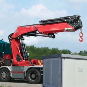
Material Lifting
-
Unloading can be done via forklift or crane
-
If obstacles exist (trees, fences, cables), a larger crane is required
-
Send a sketch/photo for accurate lifting calculations
- An initial setup is required, along with 0.5 hours of crane or forklift operation
Dimensions:
All listed dimensions are in Length × Width × Height.
Images may not accurately reflect the actual color of the products.
Not sure what you need? Purchase a Phone Support Package, and we will help you!